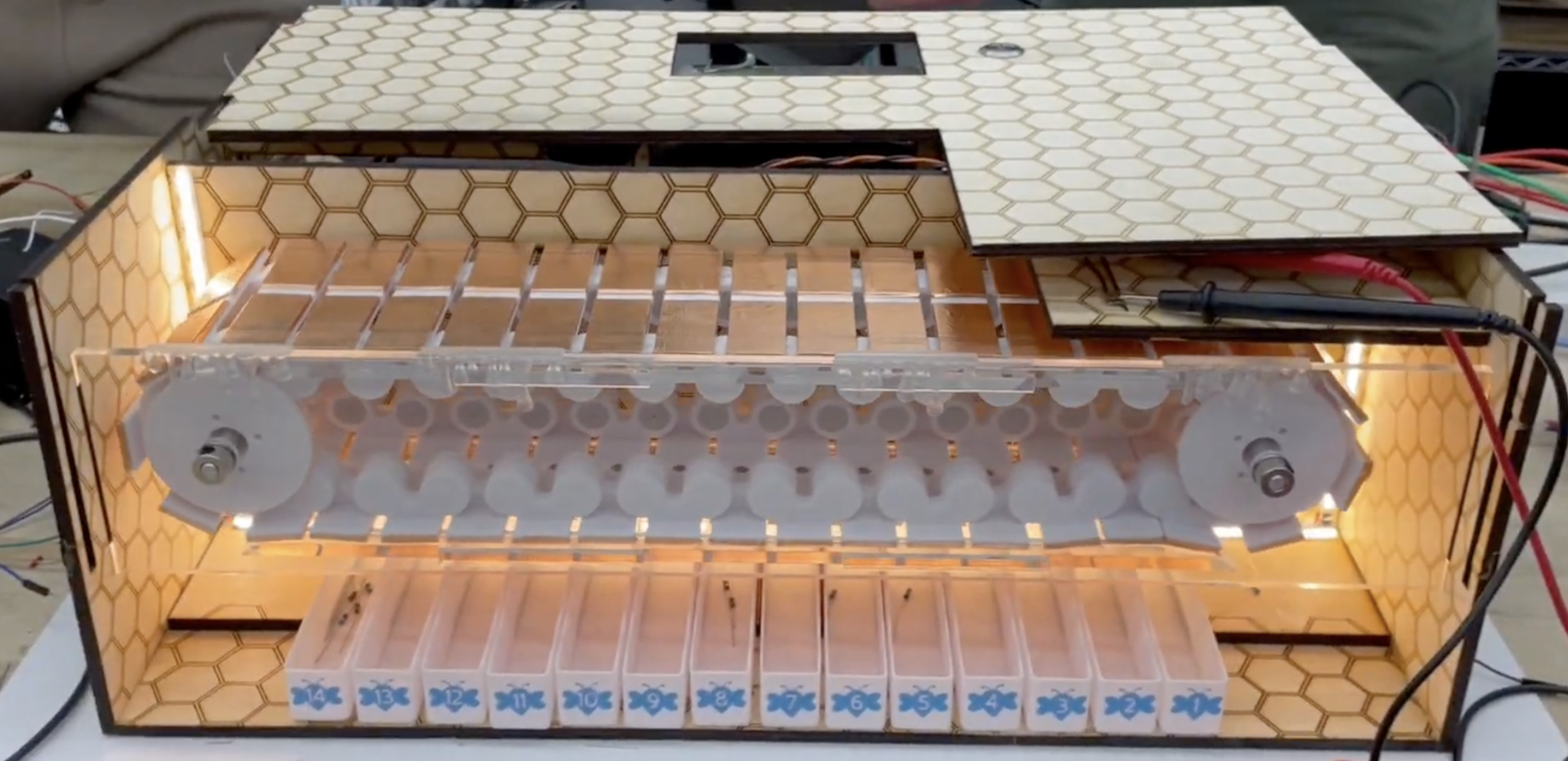
Automated Resistor Sorter
Overview
Worked on a 6 person multidisciplinary team to build a through hole resistor sorter. Designed to automatically measure, and sort bulk resistors into specific bins based on their ohm values.
My Role & The Tech Stack
- Role: Electrical & Firmware Engineer
- Hardware: KiCad, Custom PCB, AVR MCU, Stepper Motor, 12 linear actuators
- Software: C++, Serial Debugging, python
- Skills: Analog-to-Digital Conversion (ADC), Hardware Debugging, Multidisciplinary Integration, Power distribution
The Engineering Process
1. Overview
We designed a conveyer belt system the tests through hole resistors and puts them in specific bins. Below I linked the github page for the project and for this specifically I will talk about what I did.
2. Custom PCB
To avoid “rat’s nest” of breadboard wiring, I co-designed a custom PCB in KiCad. This board served as the central nervous system for the project, consolidating the microcontroller, the analog measurement circuitry, and the motor drivers needed to control the singulation and sorting mechanisms. At first we did not want to do a PCB because they can be risky for first iteration but we decided to build this because we wanted more practice designing. We were on a time crunch so my teammate and I did both the schematic and layout day of us deciding to make this PCB. After that we had people review and gave us edits for the PCB and we sent it two days after deciding to make this PCB.
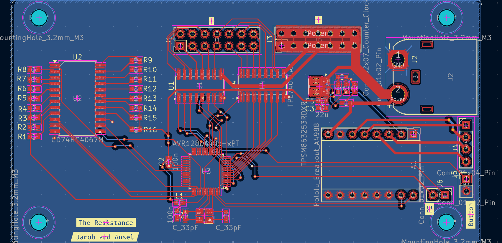 Caption: The custom PCB layout designed in KiCad, routing power and logic for the motor drivers and measurement circuits.
3. Integration & Hardware Debugging
There were some bugs with the PCB when we got it but with some botch work we got it working.
Integrating the electrical with the hopper and sorting mechanisms introduced significant challenges. We encountered issues with lots of noise from motor causing brown outs on our MCU, which had to add a capacitor to help reduce but occasionally we still would see brown outs.
I used oscilloscopes and multimeters to trace voltage drops and isolate signal noise. This rapid iteration and troubleshooting process was the most intensive and educational phase of the project.
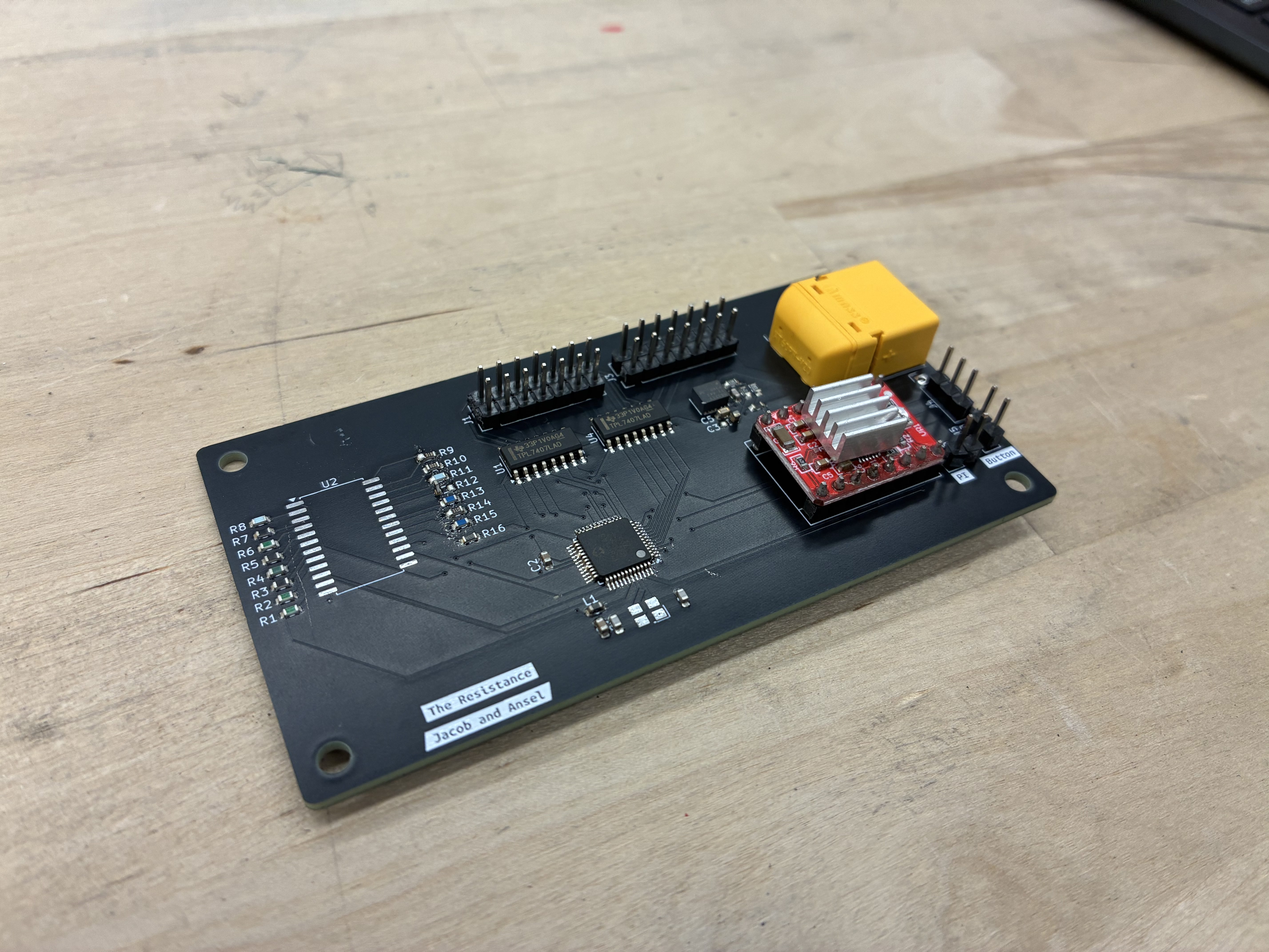 Caption: The custom PCBA.
4. Firmware
I also worked on the firmware which was broken up into three main sections: controlling conveyor belt, controlling actuators, and getting resistor values. I primarily worked on the conveyor belt code and the controlling actuators. I created a thread that would be a not stopping function for always moving the conveyor belt. There were thirteen actuators which would push off the resistors of the conveyor belt into respective buckets.
Outcomes & Lessons Learned
Ultimately, while the final integrated machine did not achieve a 100% perfect sorting success rate, the project was a massive success in terms of hardware education.
If we had another iteration to improve the system, I would not use a cheap motor controllor and use something stronger, and I would also like to add more indecators on the PCB to see what is happening. Learning how to design a PCB that survives the chaos of moving mechanical parts profoundly changed my approach to systems engineering.