FSAE Hardware
Overview
I designed and integrated four custom PCBs for Olin Electric Motorsports (Formula SAE) using KiCad. My work primarily focused on the Battery Management System (BMS), the Throttle Control board, and the Precharge/Discharge circuitry.
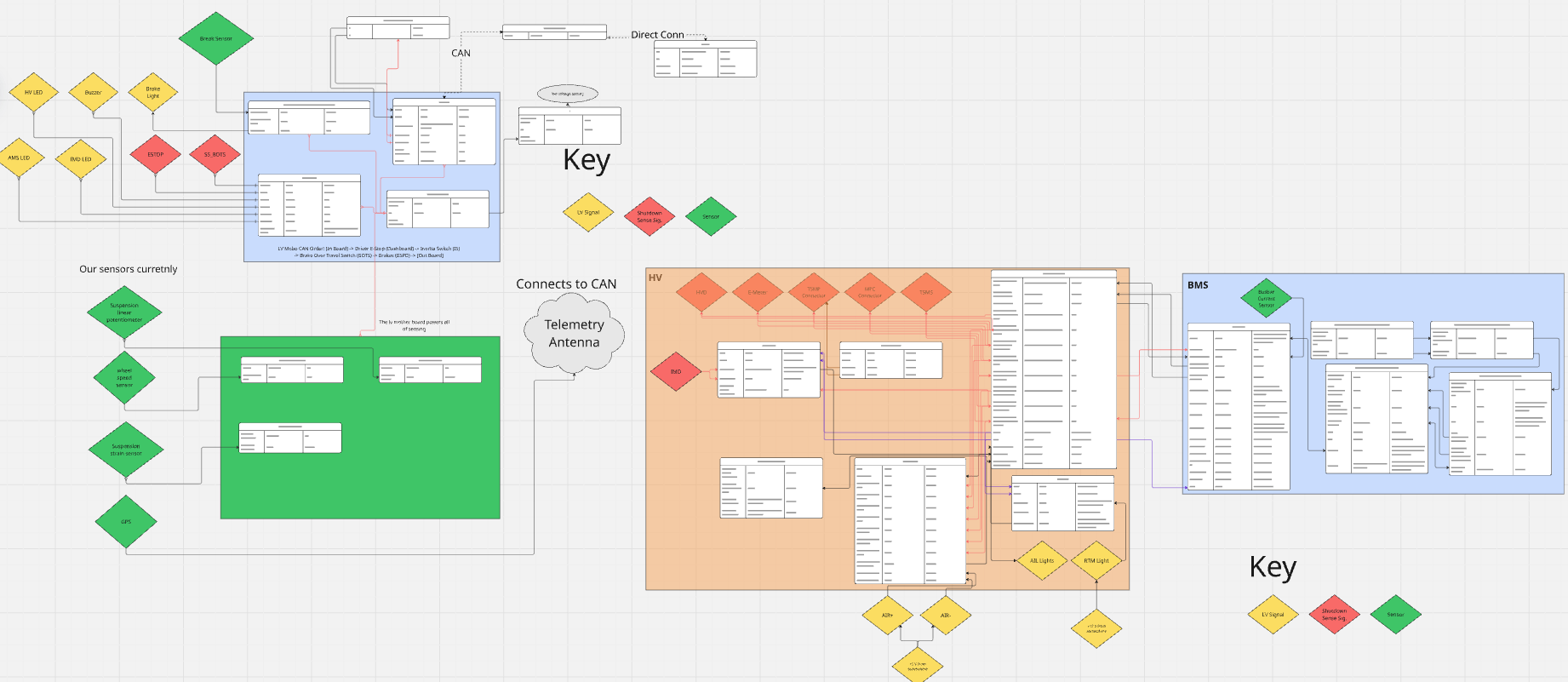
Our engineering team prioritized a highly modular vehicle architecture. In the event of a localized failure, individual systems can be rapidly isolated and swapped without rewiring the entire car. In total, the vehicle utilizes 41 PCBs (18 unique designs), four of which I personally architected from schematic to final assembly.
My Role & The Tech Stack
- Role: Hardware & Firmware Engineer (Progressed to Electrical Lead)
- Hardware: KiCad, Custom PCBs, Atmega 16m1 Microcontrollers, High-Voltage Relays
- Protocols: IsoSPI, CAN Bus, SPI
- Skills: Schematic Architecture, High-Voltage Layout, Fault Mitigation, Safety Redundancy
System Architecture
To manage the complexity of an electric vehicle, we divided our electrical architecture into four distinct subsystems:
- Low Voltage: Manages driver controls, dashboard interfaces, and low-power logic.
- Integration: Handles the physical wiring harness routing and the automated charging sequences.
- High Voltage: Manages the tractive system, accumulator safety, and power delivery to the motor.
- Sensing: Dedicated data acquisition boards that monitor vehicle dynamics to optimize performance.
Core Hardware Subsystems
Below is a detailed breakdown of the PCBs I personally engineered. As I transitioned into the Electrical Lead role, I was also responsible for conducting strict design reviews for the rest of the vehicle’s boards to ensure rules compliance.
1. Battery Management System (2 PCBs)
The BMS is the most critical safety component of the tractive system. I split this system across two distinct physical boards: the Power Thermistor board (for raw data collection and power routing) and the BMS Core (for centralized logic and safety monitoring).
Power Thermistor Board
Our team utilized donated Tesla battery cells, which required a custom accumulator design to package them safely. The primary function of this board is to map the temperature of the cells and safely route power across the battery segments.
The PCB layout was strictly governed by mechanical constraints. The mechanical sub-team designed a rigid structural housing for the cells, and I had to map the board’s footprint, mounting holes, and connector placements to perfectly align with their CAD model.
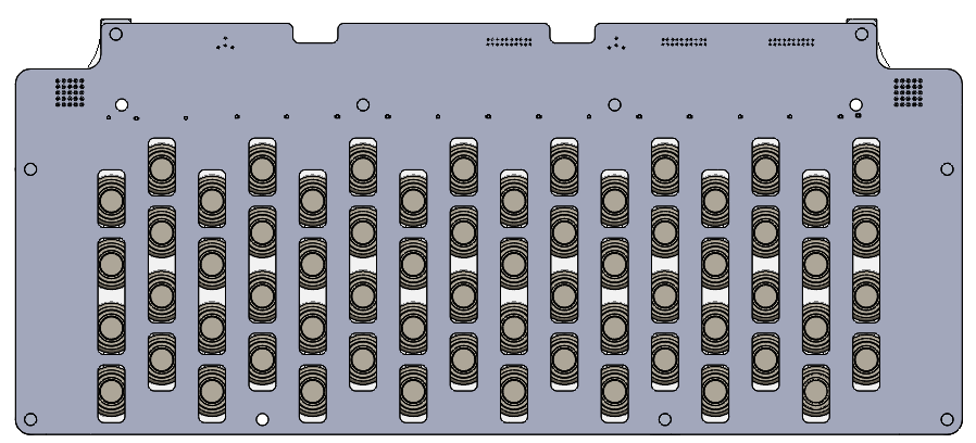 Caption: Front view of the Power Thermistor board mounted to the front of a battery segment.
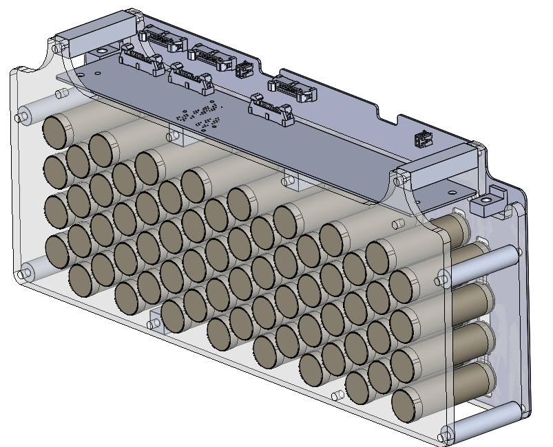 Caption: Side angle demonstrating how the PCB connectors perfectly align with the mechanical structure.
Designed as a 4-layer board, it routes the battery cells first in parallel, then in series. I utilized thick 2oz copper pours on the top layer to allow us to directly spot-weld the nickel strips from the cells to the PCB rails, minimizing electrical resistance and structural weak points.
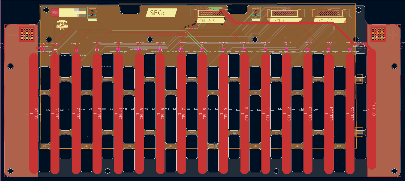 Caption: KiCad layout highlighting the heavy copper pours required for high-current routing.
BMS Core
This centralized logic board aggregates data via a Daisy-Chain IsoSPI interface, reading all thermistor and cell voltage data from the surrounding segment boards.
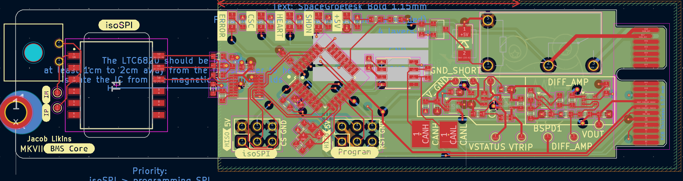 Caption: The Battery Management System Core layout.
The core architecture relies on an Atmega 16m1 microcontroller. To ensure strict rules compliance and driver safety, I integrated hardware-level ground short detection, an overcurrent sensor trigger, and a dedicated BMS shutdown relay. If the microcontroller detects a critical voltage or thermal anomaly, this relay opens and severs high-voltage tractive power instantly.
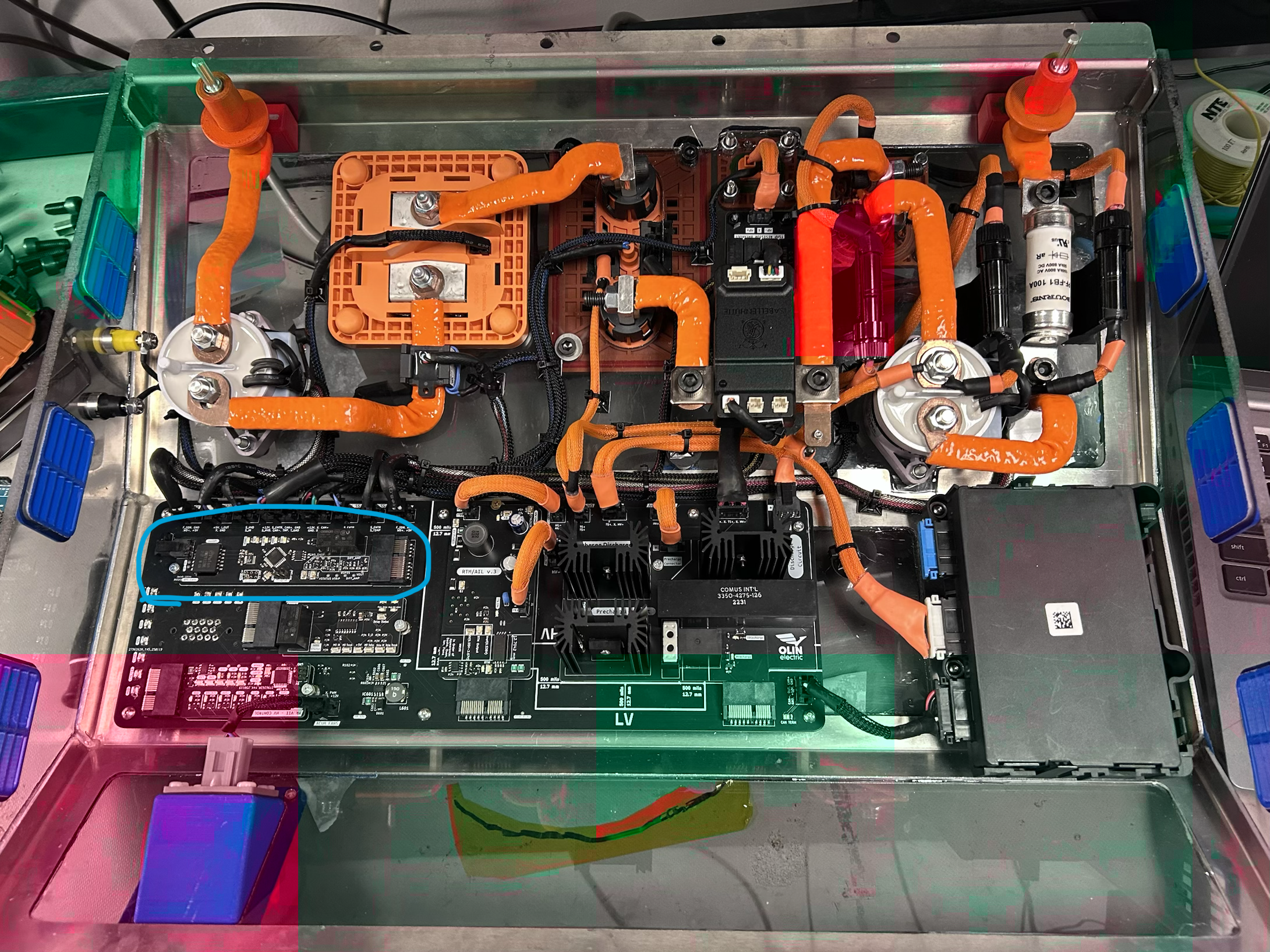 Caption: The BMS core (circled in blue) mounted within the shielded High-Voltage enclosure alongside complementary PCBs.
2. Throttle Control & Safety Redundancy
The Throttle Board reads the driver’s physical input via linear potentiometers and translates it into digital torque commands. To prevent uncontrolled acceleration, this board requires strict redundancy.
An Atmega 16m1 processes the analog signals and broadcasts the desired power level to the motor controller via the CAN bus network. For safety, the board continuously checks for “brake plausibility” by reading brake pressure sensor data over CAN, ensuring the driver is not pressing both pedals simultaneously. I also integrated a hardware inertial switch directly onto the board to trigger an immediate vehicle shutdown in the event of a rollover.
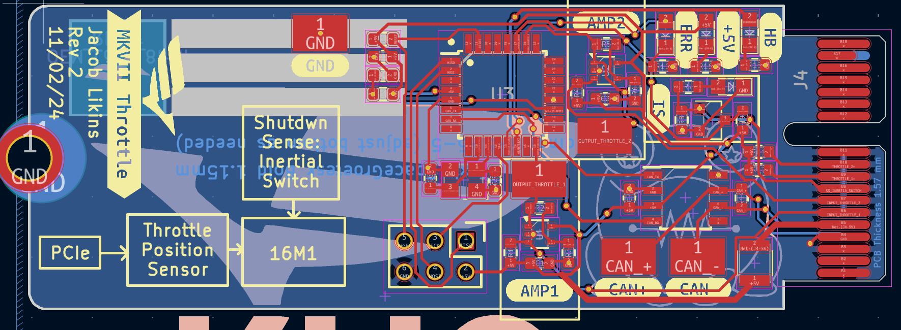 Caption: The KiCad layout for the Throttle Board, heavily optimized for a minimal footprint to fit within the pedal box.
3. Precharge & Discharge Circuitry
This board safely manages the high-voltage startup and shutdown sequences of the vehicle. Because a motor controller’s massive internal capacitors initially present as a short circuit, applying direct high voltage would cause catastrophic arcing.
To solve this, the precharge circuit utilizes high-power resistors to safely limit the inrush current, slowly charging the motor controller before fully closing the main contactors. Additionally, when the vehicle is turned off or encounters an error state, the board utilizes a dedicated discharge resistor path to safely bleed residual high voltage to ground.
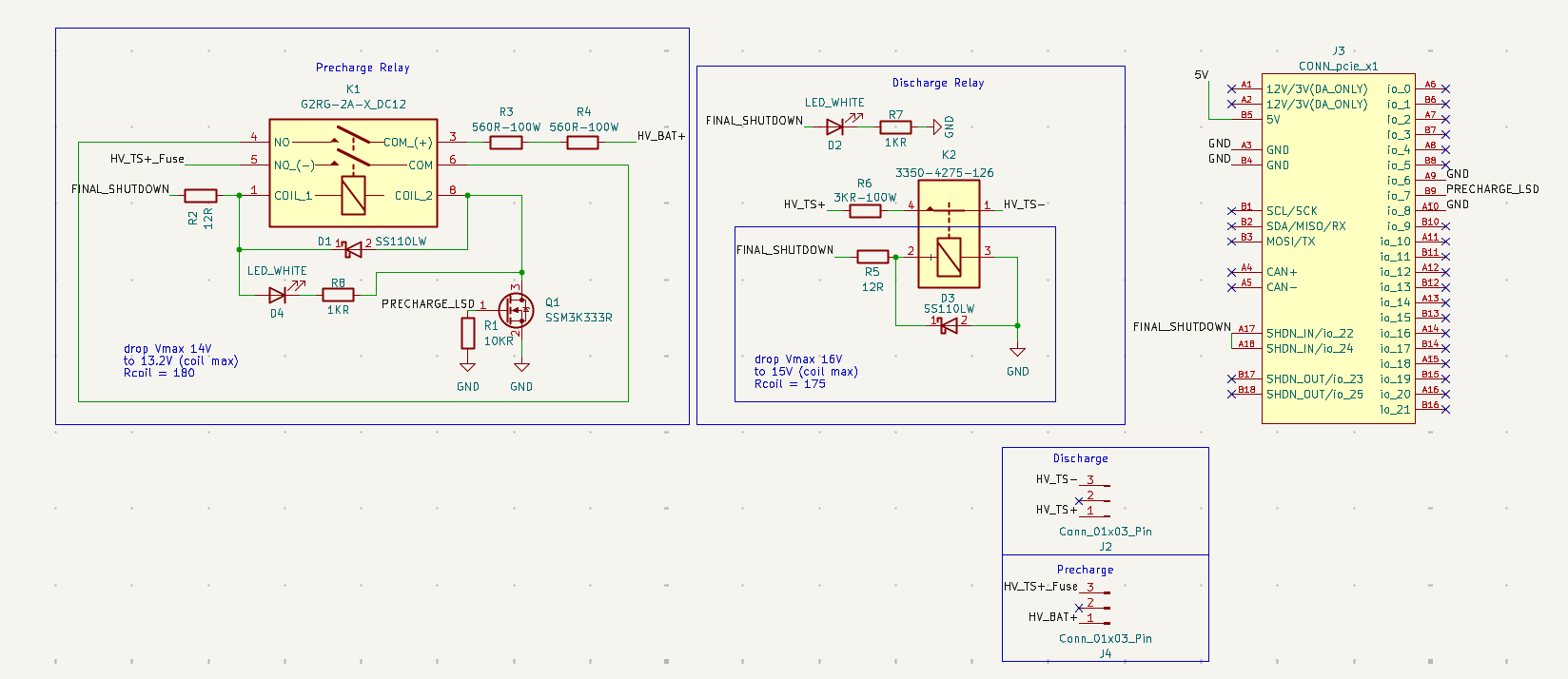 Caption: The logical block schematic for the Precharge and Discharge system.
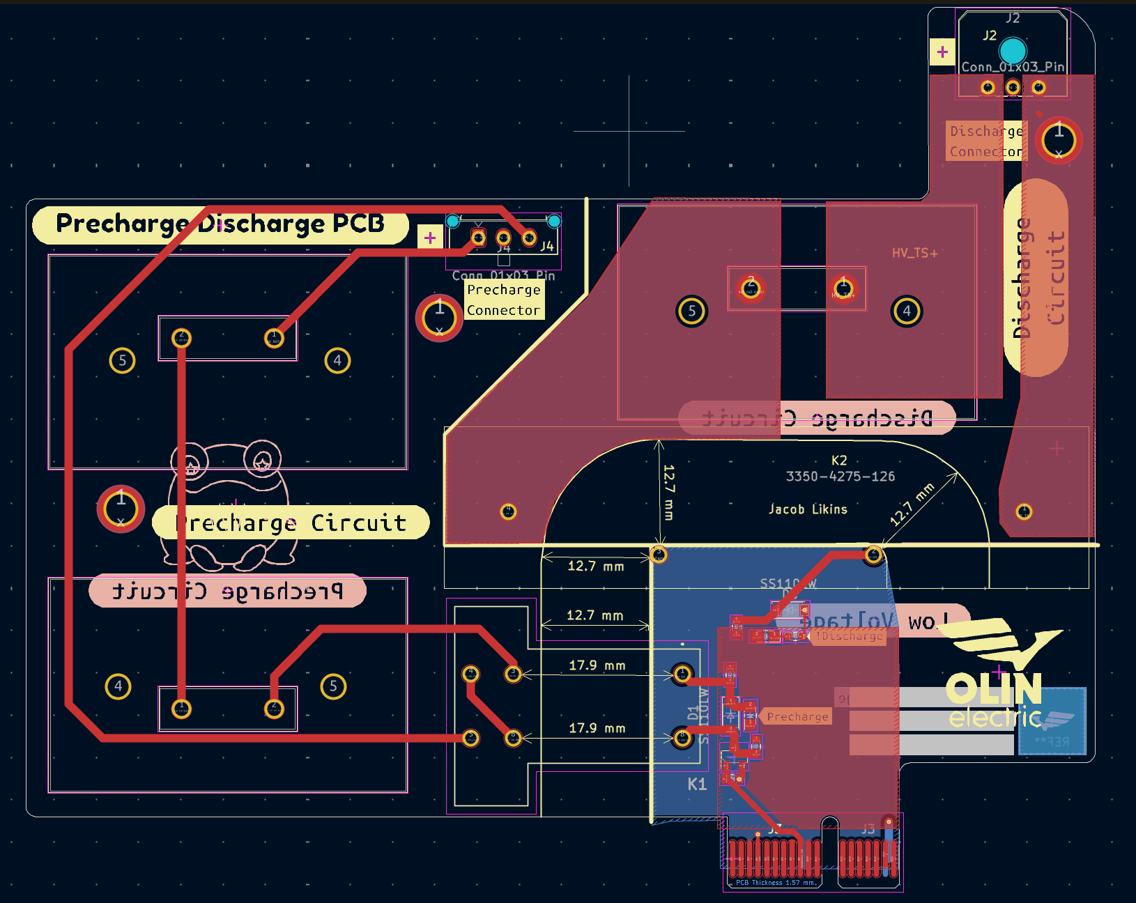 Caption: The physical board layout routing the high-voltage precharge lines.
Outcomes & Leadership Progression
Navigating the full lifecycle of these boards—from raw schematic design to strict layout routing, mechanical integration, and final manufacturing—solidified my hardware engineering foundation. The success of these sub-systems and my ability to collaborate across the mechanical and firmware boundaries directly contributed to my selection as the Electrical Lead for the following season.